The centrifugal pump is perhaps the most commonly used pump around the world, however, it is important to understand their operational limitations. Failure to do so can drastically reduce the service life of pump components.
In simple terms, a pump curve is a graphical representation of the performance characteristics of a pump. Each pump has its own pump performance curve, and what might be the perfect pump for one particular situation may be totally wrong for another.
Information is plotted on an x-y graph where the x-axis is measured in units of flow and the y-axis is measured in units of head, power, and NPSHr.
Centrifugal pump performance is represented by multiple curves indicating either:
The curve consists of a line starting at “shut head”(zero flow on bottom scale / maximum head on left scale). The line continues to the right, with head reducing and flow increasing until the “end of curve” is reached, (this is often outside the recommended operating range of the pump).
Flow and head are linked, one can not be changed without varying the other. The relationship between them is locked until wear or blockages change the pump characteristics.
The pump cannot develop pressure unless the system creates backpressure (ie: Static (vertical height), and /or friction loss). Therefore, the performance of a pump can not be estimated without knowing full details of the system in which it will be operating.
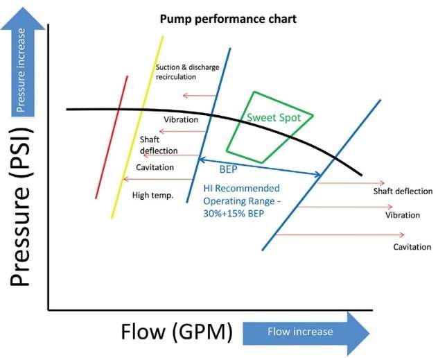
As we have mentioned, all types of pumps have operational limitations. If it operates above its given range it will damage the pump causing downtime. It is therefore essential that a pump operates at its Best Efficiency Point (BEP).
The Best Efficiency Point is not only the operating point of highest efficiency but also the point where velocity and therefore pressure is equal around the impeller and volute. As the operating point moves away from the Best Efficiency Point, the velocity changes, which changes the pressure acting on one side of the impeller. This uneven pressure on the impeller results in radial thrust which deflects the shaft causing:
The resulting damage can include shortened bearing / seal life or a damaged shaft. The radial load is greatest at shut head.
Outside the recommended operating range damage to the pump is also sustained due to excess velocity and turbulence. The resulting vortexes can create cavitation damage capable of destroying the pump casing, back plate, and impeller in a short period of operation.
When selecting or specifying a pump, it is important not to add safety margins or base selection on inaccurate information. The actual system curve may cross the pump curve outside the recommended operating range. In extreme cases the operating point may not allow sufficient cooling of pump, with serious ramifications!
The best practice is to confirm the actual operating point of the pump during operation (using flow measurement and / or a pressure gauge) to allow adjustment (throttling of discharge or fitting of bypass line) to ensure correct operation and long service life.
If you are unsure about what size pump you need please contact us. We’ll give you an honest, expert recommendation to get your pump operations running efficiently and effectively.

Contact us to learn about how we can help you with your pump needs.
CALL US NOW EMAIL US